PCB DESIGN - All In One v2.5 - 32 inputs with 74HC4851

Discussions related to MegaDrum Hardware

Re: PCB DESIGN - All In One v2.5 - 32 inputs with 74HC4851

Postby mrdutx » Mon Oct 05, 2009 7:29 am

gastric wrote:
Synthex wrote:
Juze wrote:I have the pcb now, I'm now putting components that I already have to it. Synthex, could you make a part list for this pcb? :P

You can see the list of components on the top of the PCB. It's the "same" as v2.4.


I've attached a list of V2.5 components and confirmed it with Synthex. It does only differ slightly from the V2.4 list.

I'm going to try my best to produce a complete list of all components, including cables, cable ends, case, etc. sourced from Mouser.com to hopefully facilitate easy drag-and-drop ordering of a complete 100% DIY Synthex V2.5 "kit" from within the US. However, due purely to the massive amount of products offered at Mouser.com it'll take some amount of effort to figure out which capacitors/resistors/etc. are appropriate.


can i use 1000uH instead 1mH?
and for 47uF (25v radial electrolytic or tantalum) can i use 47uF polyester capacitor 50V.

and what this 220nP (25v multilayer ceramic)?
it's 220nF ?
mrdutx
 
Posts: 23
Joined: Wed Sep 23, 2009 3:57 am

Re: PCB DESIGN - All In One v2.5 - 32 inputs with 74HC4851

Postby Firelord » Mon Oct 05, 2009 8:03 am

mrdutx wrote:can i use 1000uH instead 1mH?
See this. It's one and the same, i.e. 1mH = 1000uH.

mrdutx wrote:and for 47uF (25v radial electrolytic or tantalum) can i use 47uF polyester capacitor 50V.
Generally if an electrolytic (or tantalum) capacitor is required by the design, then it must be used.

mrdutx wrote:and what this 220nP (25v multilayer ceramic)?
I guess it's a typo and indeed it is 220nF.
Firelord
 
Posts: 666
Joined: Wed Jun 10, 2009 7:50 pm
Location: Estonia

Re: PCB DESIGN - All In One v2.5 - 32 inputs with 74HC4851

Postby mrdutx » Tue Oct 06, 2009 6:20 pm

i'm working my pcb in lab PCB making.
i'm using the machine for drill. it can drill all hole in pcb by setting the drill size.

i want to know the size of the hole in pcb board
mrdutx
 
Posts: 23
Joined: Wed Sep 23, 2009 3:57 am

Re: PCB DESIGN - All In One v2.5 - 32 inputs with 74HC4851

Postby Firelord » Tue Oct 06, 2009 6:57 pm

mrdutx wrote:i'm working my pcb in lab PCB making.
i'm using the machine for drill. it can drill all hole in pcb by setting the drill size.

i want to know the size of the hole in pcb board

I use drilling bits from 0.8mm to 1.0mm for drilling PCB's. Sometimes you may need larger bits, say, for the USB jack case pins or PCB mounting holes.
Firelord
 
Posts: 666
Joined: Wed Jun 10, 2009 7:50 pm
Location: Estonia

Re: PCB DESIGN - All In One v2.5 - 32 inputs with 74HC4851

Postby mrdutx » Tue Oct 06, 2009 7:01 pm

Firelord wrote:
mrdutx wrote:i'm working my pcb in lab PCB making.
i'm using the machine for drill. it can drill all hole in pcb by setting the drill size.

i want to know the size of the hole in pcb board

I use drilling bits from 0.8mm to 1.0mm for drilling PCB's. Sometimes you may need larger bits, say, for the USB jack case pins or PCB mounting holes.


thank firelord
mrdutx
 
Posts: 23
Joined: Wed Sep 23, 2009 3:57 am

Re: PCB DESIGN - All In One v2.5 - 32 inputs with 74HC4851

Postby mrdutx » Wed Oct 07, 2009 10:57 am

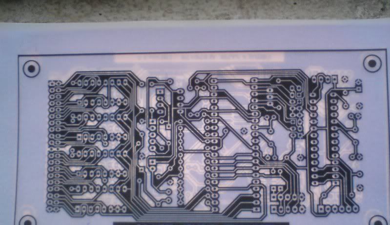
today i'm done doing pcb board..but it not finished. the was problem in the process. i printed the pcb layout from dmitri..here the film that i use.Image
this circuit is very complex!
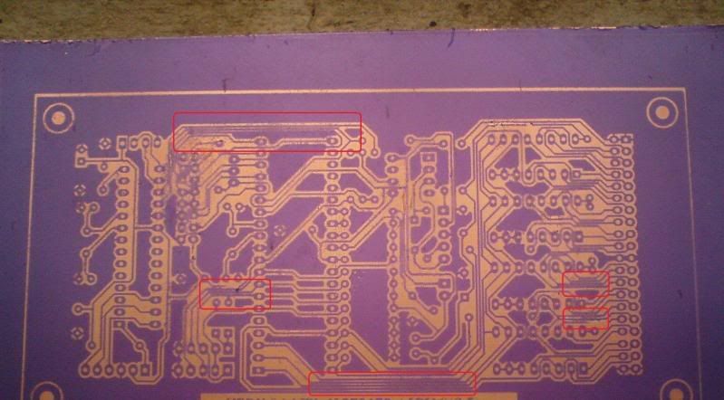
the problem is..after done the developer process.
the circle in the pcb is the problem ..can anyone tell me why this happen and what are the solution.
Image
the line is too close
mrdutx
 
Posts: 23
Joined: Wed Sep 23, 2009 3:57 am

Re: PCB DESIGN - All In One v2.5 - 32 inputs with 74HC4851

Postby Firelord » Wed Oct 07, 2009 2:34 pm

Did you invert the layout? Are yellow traces actually copper on your second picture? :shock:
Firelord
 
Posts: 666
Joined: Wed Jun 10, 2009 7:50 pm
Location: Estonia

Re: PCB DESIGN - All In One v2.5 - 32 inputs with 74HC4851

Postby mrdutx » Wed Oct 07, 2009 2:59 pm

Firelord wrote:Did you invert the layout? Are yellow traces actually copper on your second picture? :shock:


yes..it hv been invert..this process is not finish yet. this just develop process..after itching process it will be invert back..
yess..yellow are copper..
mrdutx
 
Posts: 23
Joined: Wed Sep 23, 2009 3:57 am

Re: PCB DESIGN - All In One v2.5 - 32 inputs with 74HC4851

Postby JunRin » Wed Oct 07, 2009 4:28 pm

Hi Synthex,

First of all thanks for you hardwork making this project a success :mrgreen:
And also of course to Dimitri for making this website known to the whole world :mrgreen:

Since two days ago i'm trying getting some ideas on this mega drum on how it works.
And i found out that is just easy way to build this mega drum (just kidding :lol: ).

Anyway my questions is:

1.) What are the firmware, bootloader programming MCU's etc,. must be use on this All-in-one 2.5 - 32 inputs
2.) How sensitive is the response's of piezos compare to the one that Dimitri designed using some BAT diodes?

Sorry for my two questions, i dont know if above questions already on the forum, but i need your expertized.

JunRin
JunRin
 
Posts: 19
Joined: Mon Oct 05, 2009 2:25 pm

Re: PCB DESIGN - All In One v2.5 - 32 inputs with 74HC4851

Postby Synthex » Wed Oct 07, 2009 4:37 pm

Thank you ! ;)

JunRin wrote:1.) What are the firmware, bootloader programming MCU's etc,. must be use on this All-in-one 2.5 - 32 inputs

You can use Atmega32, Atmega324 or Atmega644, with the 32 inputs firmware.

JunRin wrote:2.) How sensitive is the response's of piezos compare to the one that Dimitri designed using some BAT diodes?

It's the same.
Synthex
 
Posts: 1471
Joined: Fri Oct 12, 2007 6:06 am
Location: France

PreviousNext

Return to MegaDrum Hardware

Who is online

Users browsing this forum: Google [Bot] and 60 guests