Rockdudes Yamaha 3 zone replica for MegaDrum (build log)
I've finally decided to try to make a Yamaha 3 zone replica for my MegaDrum. I'll try to follow Kimouette's version of Elrules version 
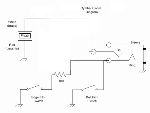
Here's Kimouettes simplified and modified circuit diagram of the original Yamaha PCY-150s:

And here's a link to some pictures of her building it:
http://picasaweb.google.ca/Kim.Tanguay/AToECymbal3ZoneYamahaReplica#
I'm not really sure I've understood everything correctly. So please bear with me and help me out if you see anything spooky.
I've created a bell switch and an Edge switch made of a thin plastic mat and piece of brass.
Here's an overview: I just laid it out so it would be easier for me to see how everything is connected. The brass parts of the bell and edge switches will of course face the cymbal later and the piezo will be situated under the cymbal.

Bell switch:

Edge switch:

Piezo:

I've read through a few threads both here and at vdrums.com to get the grip of this build.
Here's a good text explaining how it works that I found here in the MegaDrum forum:
"If the edge is hit, the switch closes and the piezo picks up the vibration and produces the assigned sound for an edge hit. This would go the same for the bell. If neither of the switches are closed but the piezo is picking up vibration, then it will produce sounds based on the bow hit. The 10k resistor is used to separate the edge and bell switch. This is done by changing the voltage that it registers across the piezo. For the choke, when the edge is held, MegaDrum will then decipher the switch being closed and not momentary and choke out the sound.
I'm a little unsure about how to interpret the switches. Do I have to ground both the bell switch and the edge switch separately like I've done in my pictures above?. Or is it sufficient to connect one wire from sleeve of jack to the cymbal and that will ground both the edge and bell switch at the same time. Isn't it basically one switch consisting of two switch parts (edge and bell)?
Here's Kimouettes simplified and modified circuit diagram of the original Yamaha PCY-150s:
And here's a link to some pictures of her building it:
http://picasaweb.google.ca/Kim.Tanguay/AToECymbal3ZoneYamahaReplica#
I'm not really sure I've understood everything correctly. So please bear with me and help me out if you see anything spooky.
I've created a bell switch and an Edge switch made of a thin plastic mat and piece of brass.
Here's an overview: I just laid it out so it would be easier for me to see how everything is connected. The brass parts of the bell and edge switches will of course face the cymbal later and the piezo will be situated under the cymbal.

Bell switch:

Edge switch:

Piezo:

I've read through a few threads both here and at vdrums.com to get the grip of this build.
Here's a good text explaining how it works that I found here in the MegaDrum forum:
"If the edge is hit, the switch closes and the piezo picks up the vibration and produces the assigned sound for an edge hit. This would go the same for the bell. If neither of the switches are closed but the piezo is picking up vibration, then it will produce sounds based on the bow hit. The 10k resistor is used to separate the edge and bell switch. This is done by changing the voltage that it registers across the piezo. For the choke, when the edge is held, MegaDrum will then decipher the switch being closed and not momentary and choke out the sound.
I'm a little unsure about how to interpret the switches. Do I have to ground both the bell switch and the edge switch separately like I've done in my pictures above?. Or is it sufficient to connect one wire from sleeve of jack to the cymbal and that will ground both the edge and bell switch at the same time. Isn't it basically one switch consisting of two switch parts (edge and bell)?